| USPEX 10.5 manual |
| USPEX 10.5 manual |
Prediction of a phase transition mechanism can be considered as a double-ended problem, in which the algorithm has to locate the intermediate states. The nudged elastic band (NEB) 32; 33; 34 method is a widely used technique for solving double-ended problems, an efficient and robust approach for seeking reaction paths and saddle points along the “minimum energy path” (MEP) on the potential energy surface between the two endpoints. The NEB method has been successfully applied to study molecular chemical reactions, and defect migration, and in principle it could provide the energy barrier between the given initial and final states of a phase transition process. Unfortunately, most of the problems treated by the NEB method are considered under the constraint of constant unit cell — which precludes it from being used for phase transitions (which involve the variation of the unit cell along the transition path).
![\includegraphics[scale=0.95]{pic/VCNEB.png}](images/img-0145.png)
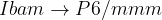
 are shown in the inset.
  is the potential force in the gradient direction.
  and
and  are the transverse component of and the spring force, respectively.
The variable-cell NEB (VCNEB) method 14, which we have developed, treats the cell and atomic coordinates on an equal footing and operates in an expanded configuration space under the condition of constant pressure. Our VCNEB method framework has been added to the USPEX code in 2013. The VCNEB method is a more general tool for exploring the activation paths between the two endpoints of a phase transition process within a larger configuration space. Every structure on the pathway in the VCNEB method is regarded as an “Image”.
The VCNEB method is only enabled with the VASP, GULP and Quantum Espresso codes at the moment.
To switch on the VCNEB mode, you have to:
Specify
VCNEB : calculationMethod
Create a file Images in the VASP5 format in your folder (VCNEB requires at least two structures, initial and final phases, to run the phase transition pathway prediction).
Specify the following VCNEB options:
 variable blue vcnebType
Meaning: Specifies type of the VCNEB calculation. This variable consists of three indices: calculation mode, image number variability, and spring constant variability:
calculation option:
“1” — the VCNEB method;
“2” — structure relaxation mode with no VCNEB calculation.
Variable-Image-Number method:
“0” — the number of images in VCNEB calculation is fixed;
“1” — the number of images in VCNEB calculation is variable.
variability of spring constant:
“0” — fixed spring constant;
“1” — variable spring constant.
Default: 110
Format:
111 : vcnebType
NOTE: If vcnebType=111, i.e., a calculation for VCNEB calculation with variable number of Images and variable spring constant is to be performed. We strongly suggest users to run a variable number of images in VCNEB calculations when investigating reconstructive phase transitions.
variable blue numImages
Meaning: Initial number of images to perform the calculation.
Default: 9
Format:
13 : numImages
variable blue numSteps
Meaning: Maximum number of VCNEB steps.
Default: 600
Format:
500 : numSteps
Notes: (1) When numSteps=-1, the initial pathway will only be generated with no further optimization. (2) Convergence of VCNEB pathways is usually rather slow. We recommend to set numSteps to at least 500.
variable blue optReadImages
Meaning: Options for reading the Images file:
“0” — All images (numImages) are needed and specified in Images file;
“1” — Only initial and final images are needed and would be read in Images file;
“2” — The initial, final and any specified intermediate Images will be read in Images file.
Default: 2
Format:
1 : optReadImages
NOTE: In all options, the initial and final images must be specified. Automatic linear interpolation will be applied to generated the initial Images in option 1 and 2.
variable blue optimizerType
Meaning: Optimization algorithm option of structure relaxation:
“1” — Steepest Descent (SD);
“2” — FIRE (Fast Inertial Relaxation Engine) Algorithm 35.
Default: 1 (SD) — for VCNEB calculations; 2 (FIRE) — for structure relaxation
Format:
1 : optimizerType
variable blue optRelaxType
Meaning: Structure relaxation mode:
“1” — relax only atomic positions (with cell fixed), e.g. as in the classical NEB method;
“2” — relax only cell lattice (used only for testing);
“3” — full relaxation of atomic positions and cell.
Default: 3
Format:
3 : optRelaxType
variable blue dt
Meaning: Time step for structure relaxation.
Default: 0.05
Format:
0.1 : dt
NOTE: If dt is very small, the calculations will be very slow. If dt is too large, the calculation will be unstable and may generate meaningless results.
variable blue ConvThreshold
Meaning: Halting criteria condition for RMS (Root Mean Square forces) on images.
Default: 0.003 eV/
Format:
0.005 : ConvThreshold
variable blue VarPathLength
Meaning: Criterion for path length between images for variable Image method. When the length between two neighbor images is larger than 1.5 times of VarPathLength, a new image will be added between the two images using linear interpolation; when less then 0.5 the value, the second image will be removed.
Default: The average path length between images of the initial pathway
Format:
0.3 : VarPathLength
variable blue K min
min
Meaning: Minimum spring constant, only used in variable-spring constant VCNEB (in eV/ ).
).
Default: 5
Format:
3 : Kmin
variable blue Kmax
Meaning: Maximum spring constant, only used in variable-spring constant VCNEB (in eV/).
Default: 5
Format:
6 : Kmax
variable blue Kconstant
Meaning: Spring constant, Only used in fixed-spring constant VCNEB (in eV/).
Default: 5
Format:
4 : Kconstant
variable blue optFreezing
Meaning: Option for freezing the Image structure. Image structure will be frozen when ConvThreshold is achieved if enabled. Image structure freezing options:
“0” — no Images freeze any time;
“1” — freeze when ConvThreshold is achieved.
Default: 0
Format:
1 : optFreezing
variable blue optMethodCIDI
Meaning: Option for Climbing-Image (CI) and Descending-Image (DI) method. This method is only suggested to be used when you have a reasonable and well converged pathway. CI/DI-Image method options:
“0” — CI/DI method not used;
“1” — single CI method, only the highest energy or user-provided transition state (TS) will be used for CI;
“-1” — single DI method, only the lowest energy or user-provided local minimum state (LM) will be used for DI;
“2” — mixed multi-CI/DI method, the sequential numbers of TS and LM states need to be provided;
Default: 0
Format:
1 : optMethodCIDI
variable blue pickupImages
Meaning: Number of images to be picked up for CI/DI method.
Default: Image number of transition state and local minima state Images
Format:
% pickupImages
9 11 17
% EndPickupImages
NOTE: In this case, the 9 , 11 and 17 images will be picked up for applying CI/DI-Image method. The image at transition state will evolve with CI method and the image at local minimum will evolve with DI method automatically.
variable blue FormatType
Meaning: The format of structures in pathway output file, locates in results1/PATH/. Pathway structures output format:
“1” — XCRYSDEN format (.xsf file);
“2” — VASP POSCAR;
“3” — XYZ format with lattice.
Default: 2
Format:
1 : FormatType
variable blue PrintStep
Meaning: Save the VCNEB restart files located in results1/STEP/ every PrintStep steps.
Default: 1
Format:
10 : PrintStep
NOTE: For forcefield codes, such as GULP, we suggest users to set PrintStep=10 to reduce time cost of saving the restart files.
![\includegraphics[scale=1.01]{pic/VCNEB_BH.png}](images/img-0151.png)
 transition of BH at 168 GPa 14. A
  intermediate phase is revealed. The saddle points on
 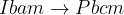 and
and 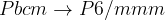 segments have barriers of 0.32 and 0.19 eV/f.u., respectively.
Fig. 16 shows an example of use of the VCNEB method: phase transition mechanism and energy barrier with the transition of BH at 168 GPa, here we obtained a intermediate phase.
The VCNEB method is very efficient for finding the phase transition path, but we must also carefully prepare the initial path. Cell rotations happen near the initial and final structures during the VCNEB calculation, where the pathway includes a lot of identical structures near the initial and finial images. We improved Variable-Image-Number method will prevent cell rotations automatically, which saves quite a lot of time.
Alternatively, you can apply the rotation-avoiding technique before you apply the VCNEB method when generating the initial image set. The general  rotation matrix with Euler angles
  and the lattice mirror operator
  matrix are defined. Before performing a VCNEB calculation, the global numerical search in space of Euler angles and mirror operator are used to find the minimal lattice cell transformation distance
  :
:
 |
(14) |
The rotation-avoiding lattice vector of the final image  is assigned as the endpoint image:
 |
(15) |
More important, we need to prevent the arbitrariness in assigning the atomic fractional coordinates  of the initial and finial images (correctly mapping the atoms at the initial and final structures). Otherwise, the calculation will be hard to converge or several identical paths can be found in a calculation, as shown in Fig. 17. For more complicated systems, you will get some unreasonable or messy pathways if you don’t have a good initial pathway. Global numerical search for minimizing the distance between the atoms from two endpoint images helps the VCNEB method to reassign the atom sequence. The ability to automatically create model paths before the VCNEB calculation is crucial for the stability and convergence of the algorithm, and is a prerequisite for studying large and complex systems.
![\includegraphics[scale=1.01]{pic/VCNEB_pathway.png}](images/img-0164.png)
 B1 phase transition in GaN at the equilibrium pressure 45.0 GPa. At images 11 and 21, B1 and B3 structures in a monoclinic cell are found during the MEP optimization. The Ga atoms move along the arrow directions during the phase transition.
| USPEX 10.5 manual |